We have seen a huge shift in computing architecture over the past
decade, with engineers opting to modularize and distribute their
services to remain agile. This approach enables quick integration
and iteration over the traditional monolithic approach to system
design. But by distributing services over the network, we trade this
development agility for processing time, as we accrue latency by
increasing the number of requests made over the network to the
various services.
The latency problem is made worse by the inflexibility of
traditional API technologies. Although new approaches to API design
have emerged to address some of these issues, adoption of these
alternatives typically requires a complete redesign of each service.
1.1 What is Synapse?
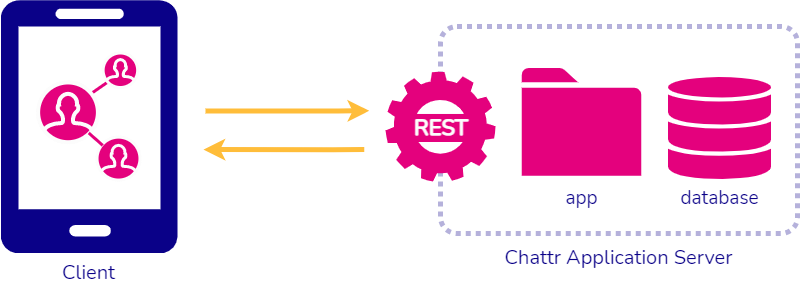
Synapse is an open-source solution for building, deploying, and
monitoring a GraphQL Gateway. Synapse enables you to put your legacy
APIs behind a single GraphQL endpoint. It allows teams to easily
deploy a new GraphQL Gateway onto AWS infrastructure and
monitor requests made to the gateway.
Synapse abstracts away the complex issues involved in adopting GraphQL by putting your
legacy backend services behind a GraphQL API gateway with a single
endpoint for client access. Developers are able to use a GUI to
configure the GraphQL gateway to include a wide variety of data sources such as REST, OpenAPI, JSON Schema, and GraphQL endpoints or databases like MongoDB and Postgres.
Our case study will examine why and how we designed and created
Synapse. Our main goal was to create a relatively easy way to turn a
complex microservice infrastructure into a single GraphQL API and
deploy it to AWS efficiently. There were many challenges we faced in
doing so and this case study will explain how we solved those
difficulties and why we made the choices we did.
First, we will explain the general web application infrastructure
and some of the problems it can present to modern day applications.
1.2 Monolithic Application Architecture
Traditionally, applications have been designed as and often start
out as monolithic applications, meaning that while the software may
have many different components, it is usually contained on one
server and tightly coupled, or interconnected, together. The
benefits of this type of architecture is that it is fairly simple to
develop, test, and deploy. It can scale up fairly well simply by
creating new instances of the application as needed behind a tool
such as a load balancer.
Fig. 1: Example Monolithic Architecture
However, the drawbacks of this architectural style become evident as
the application gets more complex and grows ever larger. Several
problems include:
Size of the application can slow start up time
Changing one part of the code can have an unanticipated ripple
effect elsewhere in the application
Reliability issues - a bug in any part could bring down the entire
application
Barrier to adopting new technologies
Must redeploy entire application if there is an update
These problems can lead to the adoption of what is known as a
microservices architecture.
1.3 Microservices Architecture
Instead of one, tightly coupled application, different services are
split into self-contained, loosely coupled microservices. Each
microservice is usually a small application unto itself that exposes
its own API for use by the other services and relies on its own
separate database if needed.
Fig. 2: Example Microservices Architecture
The main benefits of a microservices architecture include:
Less complex application since each service can be managed
independently of the others
Each service can be developed independently by a team just focused
on that service
Enables continuous deployment
Each service can be scaled independently
Developers are not bound to a specific technology for all services
One main tool that is often necessitated by a microservices
architecture is an API gateway. Since there is no longer just one
service containing all parts of the application,
this gateway is responsible for routing all incoming requests to the
proper service and providing the response.
1.4 What is an API?
An Application Programming Interface (API) provides a specification
for applications and devices to communicate with each other. For
example, an API is what allows one computer to get information from
a server or even another device. There are many ways to design and
build an API, as well as different specifications to use such as
OpenAPI, REST, JSON Schema, RPC and others.
1.5 REST APIs
One of the most common patterns for API design is REST. When one REST API endpoint does not return all the data that is
needed to fulfill the request, this results in under-fetching as the
client still requires more data from another endpoint, causing
additional network requests.
Over-fetching data may also occur and slow transmission speed when a
response contains more data than what is actually needed due to the
nature of what the REST endpoint is programmed to return.
Below is an example request to get all of a specific user’s posts
and display them with the user name who created the post. To obtain
this data we will actually need to make two separate requests. This
is because one request to the user/id endpoint does not get all the
data that is required.
Fig. 3: An example of a GET Request to /users/id
This example illustrates two problems that can occur when
interacting with a REST API. First, one request to the user/id
endpoint does not get all the data that is required and thus
under-fetches what we need.
This also shows the over-fetching problem caused by REST APIs where
we only need the user name but are getting a response that also
includes the user address and birthday.
Below we see the second network request to a different API endpoint
that is needed to fulfill the client’s main request for all posts
from a specific user. As you can see, this also over-fetches more
data than what the client is asking for by providing comments as
well. Perhaps the client only wanted the title of the posts but is
getting back the content also.
Fig. 4: An example of a second GET Request to /users/id/posts
Being unable to obtain all the data the client needs in one network
request leads to multiple requests and slower response time from an
application. So what changes could be made to reduce the number of
network requests and improve the performance of a mobile app?
First, the developer could redesign all of their API endpoints to
meet the current demands of their clients. However, client demands
change and this would require a huge amount of overhaul of their
current systems.
Second, the developer could continue to create new API endpoints for
specific and often-requested data. This would eventually lead to an
immense API back-end that is constantly growing and trying to keep
up with changing client needs.
Third, the developer could choose to move away from REST patterns and use GraphQL, a query language developed to address exactly these issues.
2. Advent of GraphQL
The inflexibility of traditional API technologies led to the
development of GraphQL. GraphQL is a strongly-typed query language
for APIs developed by Facebook in 2012 to improve the performance of
their mobile applications by defining a specification that reduced
the need to prepare data on the server and parse it on the client’s
end. It allows the client to request and receive exactly the data
that is needed, no less, no more.
Despite being a more recently developed specification, GraphQL has
quickly become adopted throughout the industry since being released
by Facebook in 2015. According to the 2021 State of Javascript
Report, the percentage of developers using GraphQL has risen from 6%
in 2016 to 47% in 2021 topping the charts with a 94% developer
satisfaction rating. Also, over 84% of developers are either
interested in learning GraphQL or would definitely use it again.
2.1 What is GraphQL?
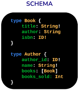
With GraphQL, the underlying available data is organized by a
schema. The schema creates a hierarchy of type definitions, which
typically represent objects. Type definitions have one or more
fields, which indicates the return type of the data.
Fig. 5: Example GraphQL API Schema
This structure and strict type system means that we can query the
schema to see the data available for querying, as well as how return
objects may be structured. It also allows us to declare exactly
which fields from a returned type are needed, meaning the client
won’t overfetch from the application.
Fig. 6: Example GraphQL Query
And lastly, the GraphQL specification allows us to perform multiple
queries in one request, even if the return types are independent,
solving the under-fetching issues and preventing the need for
multiple round-trips.
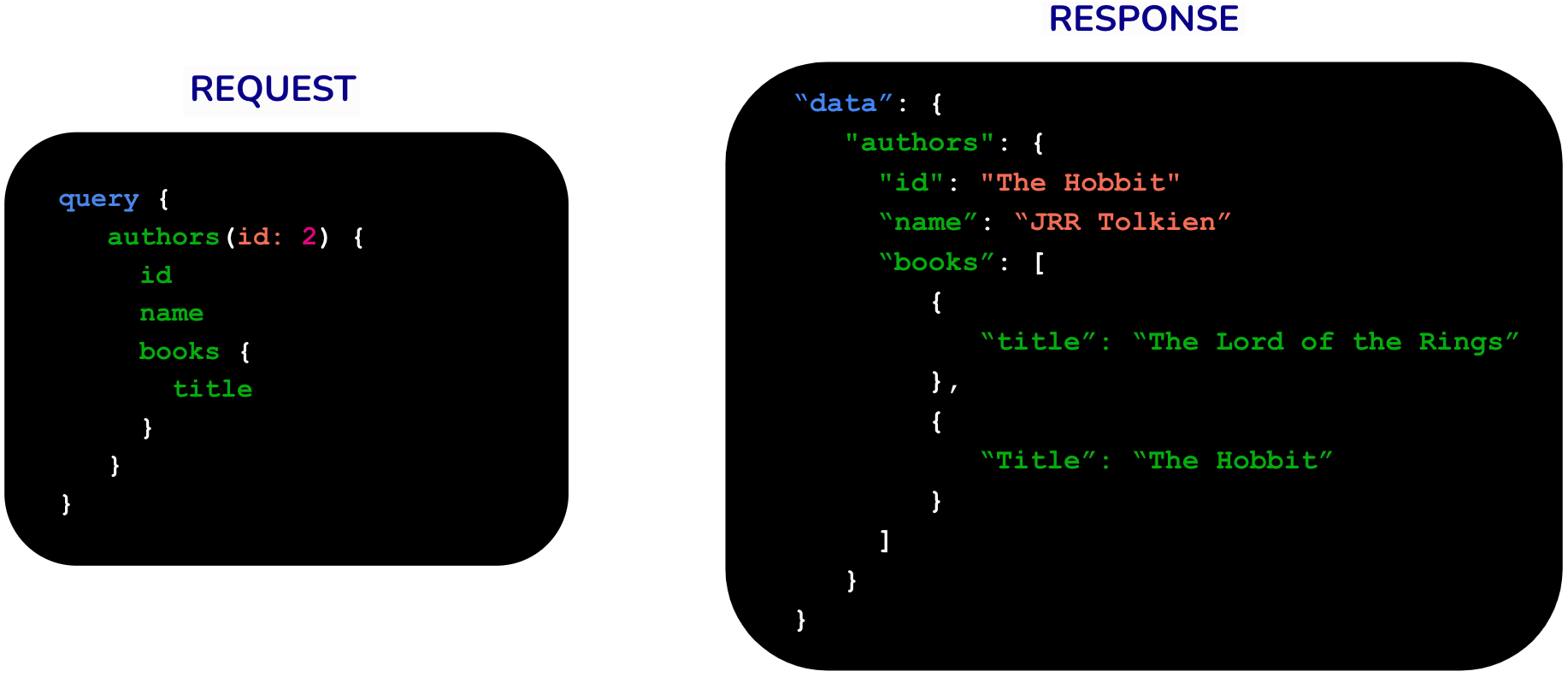
Fig. 7: Example GraphQL Response
Here is an example of a feature of GraphQL that allows nested
queries and therefore requires only one client network request to
obtain data from various resources-this prevents both under and
over-fetching. Books are related to an author, we are querying for
the authors and then sub-querying their books. Since the books are
not a scalar type but a custom type, we need to specify which of
their properties must be retrieved.
Fig. 8: Example GraphQL Nested Query and Response
In summary, the main benefits of GraphQL include:
The client can customize queries to fetch the exact data that is
needed when they need it
It reduces the over and under-fetching of data
It reduces the number of calls made over the network by the client
to the API
GraphQL provides a unified and optimized public API of services
reachable through a single endpoint.
2.2 Switching to a GraphQL API
From an existing API that is composed of many different endpoints,
how can a company switch to GraphQL? One approach would be to change
all of the current service endpoints into GraphQL. However this
would require a significant investment of time and money, as well as
a complete redesign of all service APIs to the GraphQL format.
Another common problem that would likely have to be addressed is
that some of the service APIs used by the company may in fact be
owned by third parties, such as a payment processor or email
service. These would not be available for the developer to change in
any way and have to be accessed in their current API format.
Another option would be to use a GraphQL server.
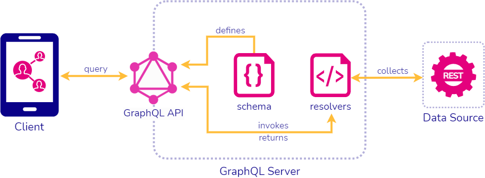
2.3 Using a GraphQL Server
When we use a GraphQL server, the client can now simply make one
request to a single endpoint for the service, reducing the need for
multiple network requests from the client to the server. The GraphQL
server uses resolver functions to access the data source and return the requested
data.
Fig. 9: Example GraphQL Server
However, the company may have several issues to deal with:
How can we integrate existing APIs without needing to redesign each one?
How can we interact with different API types like REST, Open API, JSON schema, or even databases like MongoDB or SQL?
How do we integrate third-party APIs that we cannot change?
How can we use GraphQL if our engineers have very little experience with it?
To address these challenges, we can use a GraphQL API Gateway to
access all our backend services with one request.
2.4 GraphQL API Gateway
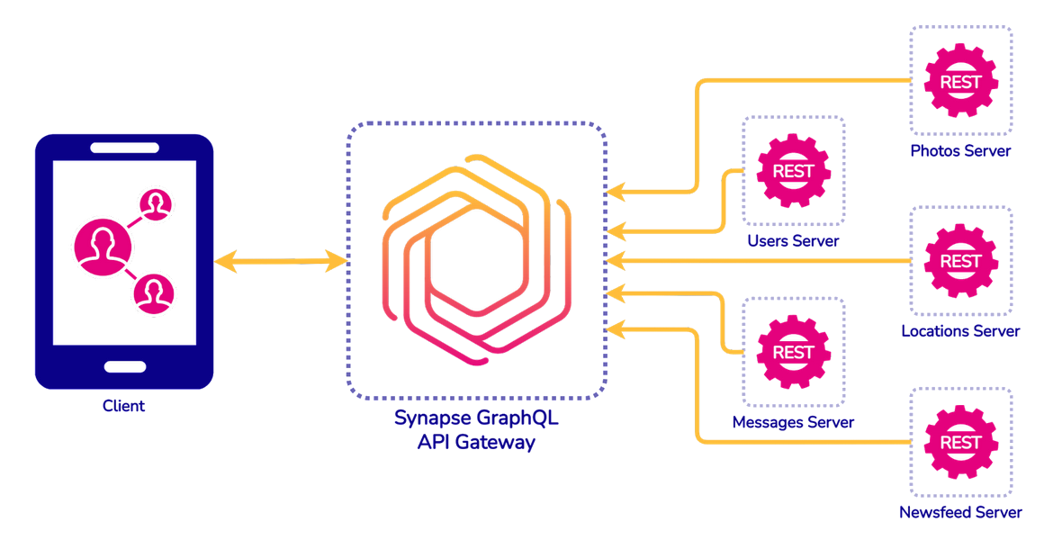
In the configuration without a gateway, you can see in the diagram
below that the client still has to make multiple trips to different
graphql servers to access each service endpoint. However, when we
use a GraphQL gateway, the client can now simply make one request to
a single endpoint, reducing the need for multiple network requests
from the client to the server.
Fig. 10: A transition from individual servers to a GraphQL gateway
A GraphQL server can functionally act as an API Gateway for
underlying data sources. Each underlying data source would have a
corresponding schema (subschema) that describes what data can be
queried from that specific source. Non-GraphQL APIs would require
resolver functions that expose this subschema - and we’ll talk more
about resolvers later.
The GraphQL gateway will aggregate these schemas into a single
schema which the client/service can now query as a single endpoint.
This solves the problem of under-fetching because all underlying
APIs are now accessible via a single client request.
2.5 Benefits of Using a GraphQL API Gateway
In summary, the benefits of using a GraphQL API Gateway include:
Having one single endpoint to query and access all data
Reducing under and over-fetching of resources from the client’s
perspective. The client can customize queries to only grab exactly
the data it needs. This is very helpful for improving the speed
and efficiency of mobile applications while reducing the number of
network requests.
A final benefit is that the gate provides a reduced attack surface
in terms of security. The focus can be enforcing security at the
gateway level rather than at each service’s API
We now need to consider the best way to actually create an API
gateway using GraphQL and how Synapse can make doing so a smooth and
simple task.
3. Creating a GraphQL Gateway
There are two possible ways to create a GraphQL Gateway: Schema
stitching and Schema Federation.
3.1 Schema Federation
To imagine how federation works it is helpful to think of one’s
underlying services as puzzle pieces. As seen in Figure 11, each
piece would be aware and designed to potentially fit together with
the others. From this, one can see that federation assumes a
company’s schema should be a distributed responsibility.
Fig. 11: Federation Puzzle Piece Analogy to combine service
schemas
To implement federation, underlying services need to be aware of
each other’s data and contain all of the logic for communicating
with one another to enable interwoven schemas, which allows for
nesting data across multiple services. Since the logic resides
within the services, the gateway acts as a thin layer responsible
for combining requested data and is able to be configured
automatically by reading the schemas of each underlying service.
3.2 Schema Stitching
To imagine how stitching works, it is helpful to think of one’s
underlying services as individual pieces of fabric. As seen in
Figure 12, the pieces of fabric are completely separate and have no
knowledge they could potentially be stitched together. The gateway
acts as the seamstress, orchestrating the combining of the pieces
into one seamless schema. For this reason, stitching assumes a
company’s schema should be a centralized responsibility.
Fig. 12: Stitching Pieces of Fabric Analogy
In stitching’s implementation, underlying services are unaware of
each other, meaning they are able to be left unaltered. The gateway
is what contains all the logic for combining services.
3.3 Stitching vs. Federation
To determine which method is best for our purpose, we need to
compare the advantages and disadvantages of stitching and
federation.
Federation allows for faster development since new changes don’t
require full coordination with other services, allowing teams to
work on different services in parallel. Additionally, federation
needs a much “thinner” Gateway layer. Since the logic for combining
services is within the services themselves, the Gateway does not
contain much logic and can be considered less of a critical piece of
architecture.
However, both of these advantages come at a cost. Federation
requires developers to alter their underlying services to contain
the logic for combining them together. Not only does this alter the
services, but requires a high learning curve for the federation
specification, which is needed to add the logic. Additionally, by
linking the services together at the service layer, each service
becomes more tightly coupled to each other.
Stitching, on the other hand, allows underlying services to be
unaltered and uncoupled from each other, as all the logic resides in
the Gateway. Each service can remain the same stand-alone service it
was before the Gateway was introduced, needing no additional logic.
Additionally, the logic in the Gateway is written in the pure
GraphQL specification, rather than using the federation
specification, which can be thought of as its own language. This
significantly lowers the learning curve to adopting a GraphQL
Gateway.
However, stitching also has some disadvantages. Since all of the
logic resides in the gateway, the gateway now becomes a much more
critical piece of architecture. Additionally, stitching results in
an increase in coordination between teams. This is because any time
a new feature is released by a team, they must make sure the feature
won’t produce a breaking change to the gateway.
Synapse uses a schema stitching solution since one
of the primary aims of our tool was to lower the skill curve of
adopting GraphQL and allowing underlying services to remain
unaltered. Let’s investigate deeper into what Synapse is.
4. Overview of Synapse
Fig. 13: Synapse is a GraphQL Gateway
As seen in Figure 13, Synapse is a GraphQL API Gateway solution,
which creates and deploys a GraphQL server, allowing users to
connect various types of different legacy APIs and data sources
using GraphQL and resulting in a single endpoint for clients to
query.
The primary goal behind Synapse was to provide an intuitive way to
unify legacy APIs into a single GraphQL endpoint. Additionally, our
team wanted to include some extra features, inspired by some other
GraphQL API Gateway solutions, which would make Synapse easy to use for a wide range of engineers.
First, our team aimed to have a simple and intuitive way to
configure the GraphQL Gateway. Synapse provides an intuitive GUI
interface to allow the developer to easily add their existing APIs
and data sources to the Gateway. This eliminated the need to add and
modify configuration files manually in a backend directory or
require learning the GraphQL syntax.
Additionally, our team wanted to include the option for developers
to be able to automatically deploy their configured Gateway on AWS
with minimal effort. Synapse provides a single command for deploying
to AWS once the Gateway has been configured.
Lastly, our team aimed to allow the developer an easy way to monitor
all requests coming through their new Gateway. Synapse creates a
monitoring dashboard for viewing request latencies, as well as any
errors produced by requests that hit the Gateway. We will explain
these features thoroughly later in our case study.
5. Who Should Use Synapse?
5.1 Existing Solutions
Fig. 14: Existing GraphQL API Gateway Solutions
When it comes to solutions for creating a GraphQL API gateway,
companies have a few options as seen in Figure 14. It is important
to note there aren’t really any managed solutions that use
Federation due the logic having to be interspersed within underlying
services. A small company may be able to utilize federation
themselves in a DIY fashion, but they may not have the resources or
time needed for training developers to learn the federation
specification and then reworking all their legacy APIs and data
sources. Let’s look at the options for a small company that does not
have a lot of time or resources to spend and would like to keep
their legacy APIs and data sources unaltered.
First, they could pick an integration platform as a service option
(IPaaS) such as AWS AppSync. Such a service will have a lot of
features, including an intuitive GUI interface for setting up the
gateway, as well as extensive monitoring and security features. The
downside would be that such a service could be very costly for a
small company and would limit the company’s flexibility to move
platforms in the future, inducing getting locked into a specific
vendor like AWS.
Additionally, they could choose an open-core option like GraphQL
Portal. Using this type of service, they would have the flexibility
of deploying where they want, the ease of easy configuration through
an intuitive GUI, as well as many additional features including
monitoring and security. The downside of this option would be that a
small company may not be able to afford the cost of using the full
features of this service on top of the deployment cost.
Third, they could opt to create the Gateway themselves manually.
This would allow the company the freedom to host where they want,
while also creating whatever features they deem necessary for their
unique situation. However, for a small company, the complexity of
creating all the features and doing it manually may drive the cost,
in terms of training their employees and development time, much too
high. Their employees may be new to GraphQL and they may not have
the resources and time to go through the training and development
process.
Synapse was created to fill a void for a small company that may not
have all their needs met by the existing solutions.
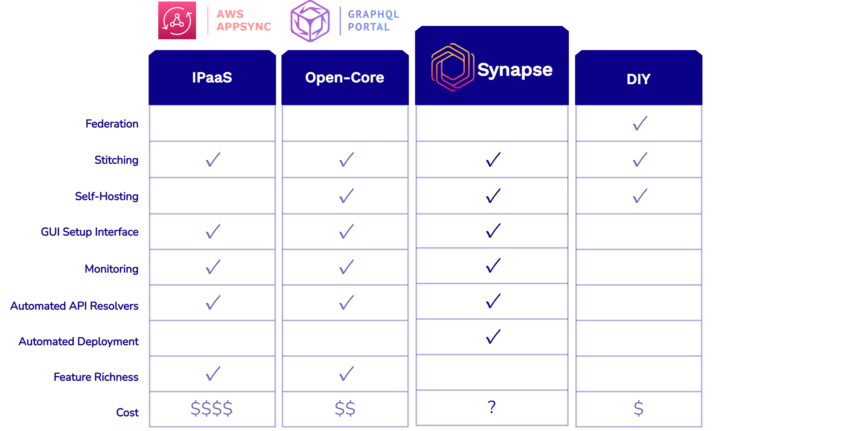
5.2 Synapse vs. Existing Solutions
Fig. 15: Solutions for a GraphQL API Gateway Solutions
As seen in figure 15, Synapse provides an easy and intuitive GUI for
configuration and monitoring, and gives the company the option to
deploy where they want. Synapse stands out by offering a feature to
automatically deploy onto AWS. The only cost involved with using
Synapse would be the cost of hosting on AWS. Everything else is free
and open source. Although Synapse looks attractive compared to other
options, it does have the tradeoff of not providing quite as many
features as other services. However, this is a tradeoff a small company
may be willing to make to keep costs low and get a GraphQL Gateway up and
connected to their existing infrastructure easily and quickly.
6. Synapse Walkthrough
Fig. 16: Four Phases of Synapse
As you can see in Figure 16, using Synapse is split into four
phases. First, the developer will download and set up Synapse on
their local machine. Then, they use the provided GUI interface, more
formally known as the Gateway Manager, to configure their Synapse
GraphQL Gateway. Once configured, the developer is able to test out
their Gateway on their local machine using the Apollo server
provided in the gateway. Lastly, if desired, the developer can
deploy Synapse onto AWS where the Synapse architecture will be
modified, preparing it for high volume traffic.
Since the architecture changes slightly in production, Synapse
technically has two states: one for configuration and one for
production. In configuration, everything is run on the developer’s
local machine. They download Synapse, and start it up on their local
machine. They then configure the GraphQL Gateway. Once configured,
the Gateway can be connected to live data sources to be tested on their local machine.
After testing of the Gateway, the developer is able to deploy
Synapse into production, where their Synapse application will now be
hosted and run on AWS. At this point, Synapse is in the production
state and the developer loses the ability to configure the Gateway
through the deployed Gateway Manager. However, this functionality is
replaced with management of users for the Gateway Manager.
Additionally, when deployed, Synapse will use a new MongoDB
database, removing all data from the configuration phase and being
seeded with the credentials of the root user. This allows the
production gateway data to be completely separate from testing data
that may have been collected during configuration.
Let’s investigate deeper, going through the four phases shown in
Figure 16.
6.1 Download and Setup
To start, the developer must first download and configure Synapse to
run on their local machine. They are able to do so by running the
command
npx @synapse-team/start-synapse. This command will
prompt the user for a couple inputs, and then will set up Synapse on
their local machine so it can be started right away.
Afterwards, the developer is able to start using Synapse on their
local machine by running the command synapse up. This
will start up and run the entire architecture on the developer’s
local machine. Keep in mind, this architecture is Synapse in its
configuration state, as shown in Figure 17.
Fig. 17: Synapse Architecture in Configuration State
Synapse consists of three components: the GraphQL Gateway, the
Gateway Manager, and MongoDB. Each part is containerized via Docker
and when the synapse up command is run, a
docker-compose file is used to start up all three containers.
6.2 Configure
Now that Synapse is running on their local machine, the developer is
able to configure and customize the GraphQL Gateway. As mentioned,
the synapse up command instantiates a containerized instance of the
Gateway Manager on the developer’s local machine. The Gateway
Manager is essentially a GUI interface that allows the developer to
configure their Gateway, with a couple additional features.
Fig. 18: How the Gateway Manager Interacts with the GraphQL API
Gateway
As you can see in Figure 18, the Gateway Manager makes changes to
the developer’s external file system on their local machine, which
updates and configures the GraphQL API Gateway. After changes are
made to the file system, the GraphQL API Gateway container is
restarted to reflect those changes. Therefore, the two don’t talk
directly to each other, but are linked by the local file system.
Fig. 19: Configuring the Gateway Through the Gateway Manager
As shown in Figure 19, the Gateway Manager lets the developer
configure the Gateway by providing a Data Sources tab where the user
can add data sources to their Gateway. They can easily add as many
data sources as they’d like with intuitive forms and tooltips
showing them what is required of them. All they have to do is add
some data sources, input the necessary files/URLs and click on
“Create Synapse” and their GraphQL Gateway will be configured and
ready to be queried. Synapse was able to do this under the hood
through the open-source tool GraphQL Mesh. GraphQL Mesh is able to
take in a variety of data sources and automatically create a unified
schema and set of resolver functions for them. We will investigate
what a schema and resolvers are and then look at how GraphQL Mesh
integrates into Synapse.
6.2.1 Schema and Resolvers
Fig. 20: Typical GraphQL Server
To explain what a schema and resolver functions are, we will follow
a GraphQL request through a typical GraphQL server, as seen in
Figure 20.
Fig. 21: Validation of Schema
As seen in Figure 21, when a request comes in, the GraphQL server
will first parse and validate the request to make sure it is
compatible with the GraphQL schema that the server is using. One can
think of the schema as a list of rules for how GraphQL requests need
to be formatted with regards to the data being requested. This
usually is manually written in accordance with the GraphQL
specification and can take a significant amount of time, even for
someone who may not be new to GraphQL.
Fig. 22: Resolver Functions Retrieve Necessary Data
If the validation passes, the server will create an execution plan
and pass off the request to the resolvers, as seen in Figure 22. The
resolvers are functions that dictate how to grab information needed
from the request. In the example shown in Figure 22, the resolver
functions would have to make requests to the correct REST API
endpoints to retrieve the necessary data for the GraphQL server to
send a response back to the client. If the data source was a
database instead of a REST API, the resolvers would be responsible
for querying that database. Usually, all of these functions would
have to be manually written by the developer and then the
information they retrieved would have to be parsed and put in the
correct format for the server to serve a response back to the
client.
6.2.2 GraphQL Mesh
Fig. 23: GraphQL Mesh Automatically Creates Unified Schema and Set
of Resolvers
As mentioned before and shown in Figure 23, GraphQL Mesh is able to
take in a variety of data sources and automatically create a unified
schema and set of resolvers for them. The way GraphQL Mesh does this
is through either introspection or taking in a specification file
that outlines a certain data source.
Introspection
Fig. 24: Introspection Request to PostgreSQL
Introspection is essentially making a request to an API or database
to gather metadata about the models or types the API itself is composed of. An example of how
GraphQL Mesh might introspect a PostgreSQL database is shown in
Figure 24. First, GraphQL Mesh makes an introspection request, which
looks at the database to see that it has a books table. GraphQL Mesh
is able to take this information and create a GraphQL schema with a
type of Book and associated subfields, as well as resolver
functions. If GraphQL Mesh was introspecting a GraphQL endpoint
instead, it would get the GraphQL schema as a response that it could
just use directly. This is why the Gateway Manager is able to have
the developer only input a URL for some data sources like GraphQL or
PostgreSQL.
Specification File
Fig. 25: Open API Specification File for REST API in Swagger
Editor (Source: SmartBear Software)
A specification file is a file in a yaml or json format that
describes all the entities supplied by a certain endpoint, as well
as all the operations for them. The example in Figure 25 shows a
specification file that defines a REST API. As you can see, this
file shows all the operations, as well as entities that those
operations apply to. GraphQL Mesh is able to use this file to
automatically create a GraphQL schema and resolvers. This allows the
Gateway Manager to only require the developer to upload one of these
files to integrate certain data sources like REST APIs.
How Synapse Uses GraphQL Mesh
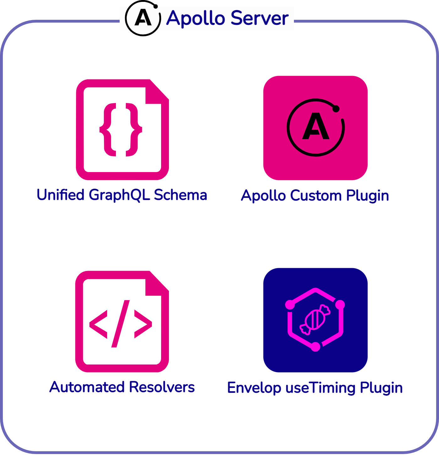
Fig. 26: Synapse Gateway is an Apollo Server Instance
The Synapse GraphQL Gateway provides a wrapper for GraphQL Mesh and
an easy way to interact with it using the Gateway Manager. As seen
in Figure 26, under the hood, the Synapse Gateway is really just an
instance of Apollo Server. Apollo provides a GraphQL library, which
includes a server, specifically an Apollo Server which is designed
specifically for GraphQL. This server is able to be instantiated as
a fully functional GraphQL server if supplied with the correct
GraphQL schema and resolvers.
Fig. 27: Synapse uses GraphQL Schema and Resolver Generated from
GraphQL Mesh
As seen in Figure 27, the Synapse GraphQL Gateway uses the automated
schema and resolver from GraphQL Mesh by passing it to an Apollo
Server instance. Apollo Server is part of the Apollo library and is
essentially a GraphQL server that can be instantiated by providing
an appropriate schema and resolver functions. In addition to the
schema and resolvers, we pass two plugins to the Apollo Server to
retrieve monitoring data from requests that hit the server. We will
go over these in more detail in the Implementation Details section.
6.3 Test
With the Gateway configured, the developer is able to test the
Gateway on their local machine.
Fig. 28: GraphQL Playground
As seen in Figure 28, a GraphQL playground is provided to the
developer when they navigate to their GraphQL Gateway on their local
machine. The playground allows them to test out sample queries and
errors to see if the gateway is working as intended.
Synapse also provides the developer the freedom to go into their
local repository and manually add extra logic to their Gateway,
which was not provided by default through Synapse. This may include,
for example, custom queries or extra permission features. If the
developer decides to do this, they only need to run the command
synapse restart after the changes are made and the
Gateway will update with their changes.
Monitoring
Additionally, the Gateway Manager provides monitoring of the GraphQL
Gateway to aid in testing, as well as to monitor production traffic.
Fig. 29: Monitoring Request Latencies Through Gateway Manager
As you can see in Figure 29, the developer is able to monitor
request latencies through the Gateway Manager. It will show the
developer their slowest requests, as well as requests within certain
time frames. These requests can be filtered by individual request,
or even by individual field resolvers to find the slowest latencies
easily and efficiently.
Fig. 30: Monitoring Errors Through Gateway Manager
As you can see in Figure 30, the developer is also able to monitor
errors through the Gateway Manager. Errors can be filtered by hour
range and provide information that includes when the error occurred,
the origin of the request that caused the error, the actual list of
errors from the request, as well as the original query that was sent
in the request that resulted in an error.
Use of MongoDB
Fig. 31: Data Stored In and Retrieved From MongoDB
All monitoring data is stored in the MongoDB, which retrieves the
data from the GraphQL Gateway, as seen in Figure 31. Our team used
MongoDB instead of a relational database for a few reasons.
First, our data was going to have a very high write-to-read ratio.
We wanted to store every request that came in, envisioning that the
user would only check the Gateway Manager for monitoring every so
often. In order to accommodate an extremely high write volume,
MongoDB seemed like a good choice as document stores scale very
well, more so than relational databases. This is because document
stores are able to be easily scaled horizontally since documents are
typically not interconnected. Relational databases, on the other
hand, are very hard to shard and scale horizontally because of how
connected all the data is to each other.
Secondly, our data was not inherently relational. The data was split
into four main collections: errors, whole requests, resolvers, and
users. None of the collections needed information from each other
and served their purpose as standalone documents. A relational
database would have been much more attractive if we had to make use
of foreign key relations, but since our data is not connected at
all, we opted for a database that would be more efficient at
handling a high volume of writes with the tradeoff of losing
increased performance if we ever wanted to connect our data in the
future.
Lastly, we did not want to adhere to the strict schemas imposed by
relational databases. GraphQL queries, by their nature, can vary
significantly, and therefore, errors and responses may sometimes
differ greatly from predetermined schemas. We wanted to go with a
database where we would be able to dump information as it came
regardless of schema since there was so much variation that could be
observed.
6.4 Deploy
With the Gateway fully tested, the developer is able to deploy their
Gateway. To start, the developer must first teardown Synapse on
their local machine by running the command
synapse restart.
Fig. 32: Synapse Automated Deployment
As seen in Figure 32, the developer then only needs to run the
command synapse deploy and their Synapse application will be
deployed on AWS in the production state. The only architectural
difference in the production state is that the Gateway Manager
container changes slightly. The functionality of adding data sources
and configuring the Gateway is no longer present and is replaced by
a User Management tab.
Fig. 33: User Management Replaces Adding Data Sources in Gateway
Manager once in Production
As seen in Figure 33, admin and root users are able to view all
authorized users and their roles and delete users at their pleasure.
In addition, they also are able to create new users and assign them
an admin or non-admin role.
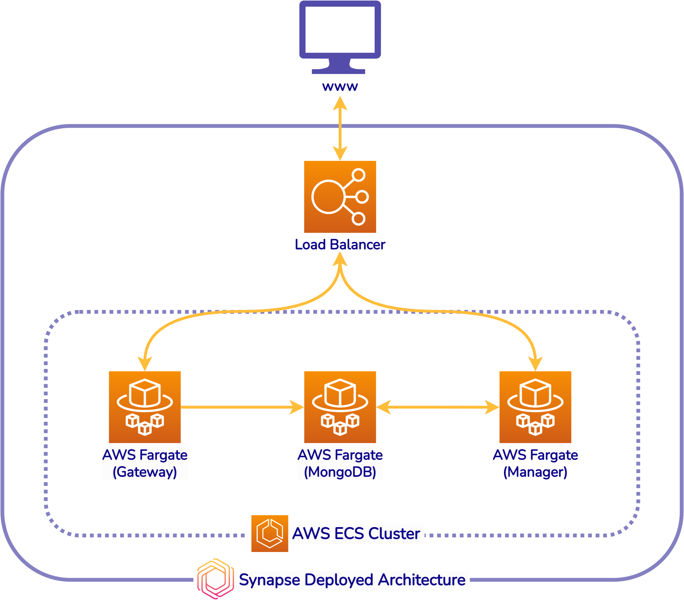
Fig. 34: Synapse Architecture on AWS
After the deployment is complete, the Synapse landscape on AWS looks
as shown in Figure 34. Each part of Synapse is put on Amazon’s
Elastic Container Registry (AWS ECS). For each part, an AWS Fargate
instance is also provisioned. Fargate is a technology that you can
use with Amazon ECS to run containers without having to manage
servers or clusters of Amazon EC2 instances. In addition, a load
balancer is created and put in front of ECS clusters that are
composed of the three containerized applications. This architecture
allows Synapse to be able to handle high volume and traffic through
AWS’ automatic scaling/descaling.
7. Implementation Details
As seen in the walkthrough, Synapse provides monitoring of requests,
as well as an automated deployment using a single command. We can
investigate further how this is possible.
7.1 Monitoring
Fig. 35: Synapse GraphQL Gateway Architecture
As you can see in Figure 35, the Synapse GraphQL API Gateway passes
two plugins to the Apollo Server instance. These plugins are what
allowed Synapse to capture monitoring data from each request.
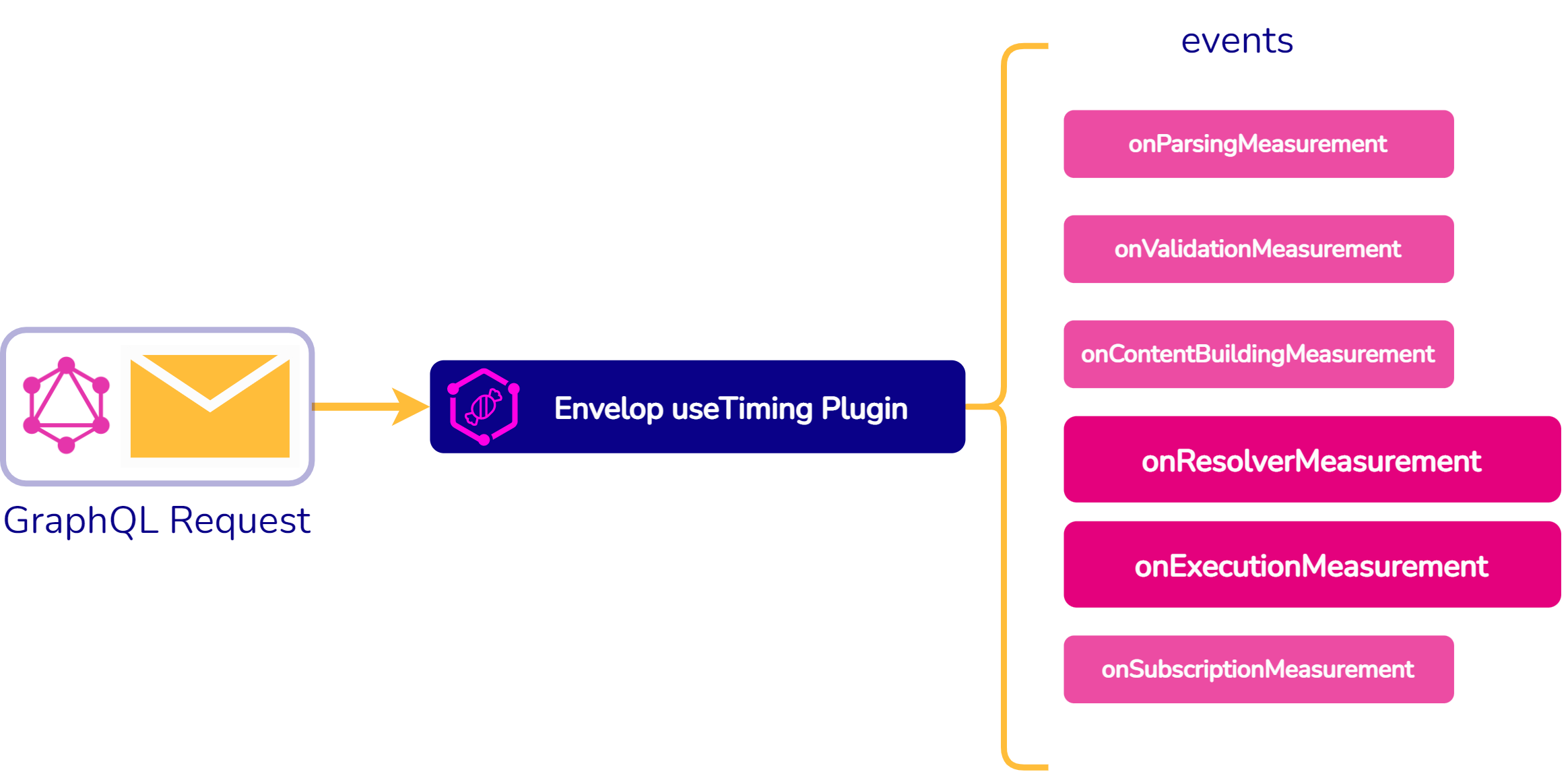
Fig. 36: useTiming Plugin from GraphQL Envelop
The useTiming plugin from the open-source tool GraphQL Envelop was
used to capture request and resolver latency data. As shown in
Figure 36, the useTiming plugin provides several events throughout
the lifecycle of a GraphQL request where data could be pulled from.
The events highlighted in Figure 36, the on-Resolver-Measurement
event and the on-Execution-Measurement event, allowed us to grab the
total request latency, as well as data on the latency of the
individual resolvers. Our team created a callback function that
captured the data we needed at these events and stored it in
MongoDB.
Fig. 37: Apollo Server Events
An Apollo Server Custom plugin was used to capture error data from
requests. Since Synapse uses Apollo Server under the hood, we were
able to take advantage of Apollo Server events to capture error
data. As seen in Figure 37, Apollo Server events are different from
the events the useTiming plugin emits, with Apollo Server emitting a
didEncounterErrors event that we were able to create a listener
for.
7.2 Deployment
Although the developer only needs to run the command synapse deploy
to deploy their Synapse application, under the hood many different
API calls are made through the Amazon CLI. This was all possible by
using AWS Copilot.
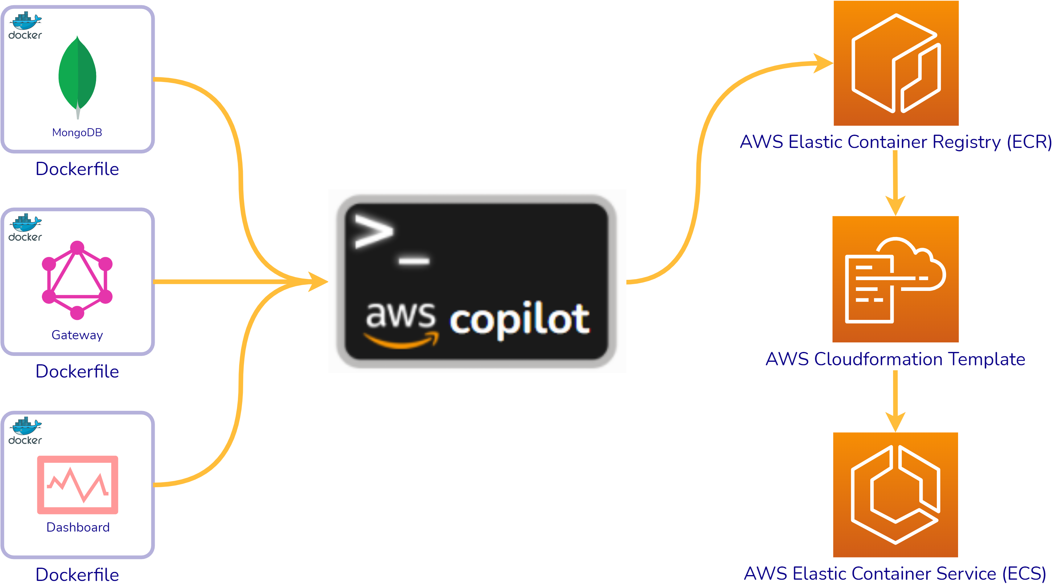
Fig. 38: Deployment via AWS Copilot
As seen in Figure 38, AWS Copilot provides a CLI that is able to
take Dockerfiles and provision the necessary resources to deploy and
put them up on AWS. Under the hood, Copilot takes the Dockerfiles
and registers them to the AWS Elastic Container Registry, which is
Amazon’s version of Dockerhub. Once the containers are registered,
AWS will generate a CloudFormation template based on some inputs to
the command line. After the CloudFormation Template is generated,
Copilot will deploy the containers onto their elastic container
service (AWS ECS) and then provision the other resources defined in
the generated CloudFormation template to make sure the application
is scalable and production-ready.
Copilot is able to do this by executing API calls to the AWS CLI
under the hood. For that reason, the only prerequisite for deploying
with Synapse is that the developer has the AWS CLI configured with
their credentials.
The Synapse CLI command synapse deploy aliases commands made to
Copilot for deployment. Additionally, Synapse automatically
provisions default settings in manifest files for AWS and provides
all the necessary Dockerfiles.
8. Implementation Challenges
ile system, external to the Synapse Architecture Our biggest hurdle
in implementing Synapse revolved around enabling communication
between containers; namely, we needed a simple means to pass the
configuration files generated by the Gateway Manager container to
the GraphQL Gateway container, as well as triggering the GraphQL
Gateway container to reload for the changes to take effect.
8.1 Containerization adds Complexity
By containerizing all three components of Synapse, we benefited in
two key ways: firstly, we were able to use Docker Compose as an
orchestrator when running the containers locally, easily spinning up
all three containers in a single terminal; and secondly, in aiding
in deployment through AWS Copilot. In using a containerized
architecture, we were able to reduce the number of deployable
components and effectively make the local and deployed versions of
Synapse identical - the containers sent to AWS are built off a
snapshot in time of the local containers.
Fig. 39: The deployed version of Synapse is a snapshot of the
local containers
However, there were also drawbacks to this approach. In putting each
major service comprising Synapse into its own Docker container, we
encountered some complexity inherent to containers: inter-container
communication and data persistence.
Inter-Container Communication
One of the benefits of containers, the fact that they are naturally
encapsulated, is also a drawback in instances where you need to
quickly establish a means to communicate between separate
containers. One way Docker enables inter-container communication is
through exposing ports, and we utilize these exposed ports to have
both the Gateway Manager and GraphQL Gateway containers communicate
with the MongoDB container. This two-way communication with MongoDB
is easy; however, our GraphQL Gateway container simply houses a
server, and would require additional logic to properly process the
requests from another container sent to its port. Communication
between containers is also possible by installing Docker inside the
Docker containers themselves (the Xzibit approach to
Dockerization), however this requires additional fumbling of permissions as well
as the skills and patience required to interact with programs
running inside a Docker container.
Data Persistence
Employing data persistence with containers is also a unique
challenge. Even if we could provide a means to directly pass
commands or files between containers themselves, the fact that
Docker containers do not persist data on their own means we require
a service external to the containers to persist the data for us.
Without a means to persist the data, an event triggering a container
to restart in deployment would result in any changes being lost and
the GraphQL Gateway would revert back to the original snapshot
produced at the time of deployment.
8.2 Sharing the Host Filesystem
Locally, a simple workaround to the inter-container communication
issue is to simply configure Docker Compose to share the host’s
local filesystem between both containers. This is done through bind
mounting the containers to a particular directory, creating a
communication link via that directory. When bind mounted (and with
proper permissions), a container can read and write to local files.
Once the changes to the local files are saved, they can immediately
be read by another container.
Fig. 40: Passing configuration files via the host’s file system,
external to the Synapse Architecture
Locally, this is the simplest approach to creating a communication
link between the Gateway Manager container, which creates the
updated schema, and the GraphQL Gateway container, which servers the
updated schema. However, it presents additional issues in
deployment.
Obviously, your local file system isn’t available for deployment to
the cloud. To mimic the communication pipeline we have locally,
Synapse would need to provision an additional cloud storage service,
such as either Amazon Elastic File System or Amazon S3, as part of
our deployment process in order to provide an adequate means to
similarly pass updated configuration files between containers. We
wanted to avoid this approach if possible, as it extended our cloud
architecture footprint, which both complicates the deployment
process and increases costs.
Local Reconfiguration
Because of the added complexity of enabling reconfiguration once
Synapse has been deployed to AWS, our team decided the best approach
was to have all configuration (and reconfiguration) of the Gateway
performed locally via the communication link created by sharing the
host’s filesystem. To do this, we removed the configuration
interface from the deployed application, and instead focused on
making redeployment as smooth as possible.
Since the functionality of adding data sources is no longer present
in production, updates such as adding a new API to the GraphQL
Gateway container are completed locally. This means the developer
must go through the previously mentioned Configuration phases again
locally.
Once the changes are complete, the updated Synapse is redeployed to
AWS using the synapse redeploy command. With the
containerized architecture, and by removing the need for a
connection between files in the Dashboard container and the Gateway
container in production, only the updated container image of the
Gateway needs to be redeployed to your AWS infrastructure. Once you
are satisfied with the changes, you can redeploy using the
synapse redeploy
command which triggers AWS Copilot to swap out the running Gateway
container with a container built using this updated image.
9. Future Work
So, where does Synapse go from here? As an open-source project, how
can our team, and others in the community, extend or build upon
Synapse?
Though Synapse is ready to use, we have three main features we would
like to see included:
Configuring cross-API resolvers through the Gateway Manager.
Currently, Synapse is focused entirely on service unification, or
onboarding APIs into a unified GraphQL schema. Assuming
well-designed APIs, this addresses the issues of over- and
under-fetching; however, the APIs themselves are not aware of each
other. We talked about this when describing the differences
between stitching and federation. Currently, pulling data from
multiple APIs can be completed via a single HTTP request, but
still requires separate GraphQL requests to each separate API. We
would like to add an interface for developers to easily add the
additional resolver logic to make types from one API available to
the returned object of another API.
Gateway Security Configuration. Another built-in
GraphQL feature we would like to provide support for is securing
portions of the unified Gateway. GraphQL can restrict parts of a
schema to only authenticated users with specified roles, and we
would like to provide a means for the Gateway Manager to easily
accommodate these configurations.
Tracking and Updating Multiple Synapses. And
lastly, we would like to implement a way to easily track and
update deployed Synapses. To easily accommodate redeployment,
users are limited to generating and deploying one Synapse per AWS
account through the Synapse CLI. Unfortunately, this means some
common workflows, such as having a staging architecture deployed
in parallel to the production version, are not currently possible.
Instead, a team would instead have to stage any configuration
changes locally, and redeploy to update their production GraphQL
Gateway container. Removing this limitation would require
extending the existing Synapse CLI in order to: generate the new
files and directories required for additional Synapses, track
these directories based on unique names provided by the user, and
handle edge cases, such as situations where local naming does not
match what AWS Copilot sees deployed on AWS.